Diagnostic procedures from car manufacturers are often centered around some basic elimination based on symptoms and diagnostic trouble codes (DTCs), and then just replacing the parts that are the most likely culprit until the problem goes away. For vague issues this does not work very well. My car has vague issues.
When getting stuck debugging a computer system it often helps to step back and work on measuring and collecting more information first. I learned the same holds true when debugging a car. Luckily modern cars already measure a ton of things, you just need to get to it.
To be a bit more specific, I’ve been chasing rough idle at cold start and irregular running for a while. I now know this is related to worn out and out-of-spec solenoids for the variable valve timing. Especially a shudder/vibration and irregular power delivery while cruising was tricky to diagnose.
The diagnostic software from the manufacturer was not very helpful here, because the problem only occurred while driving, and the live data plots are both not very good and impossible to read while driving.
What I needed was a logger that could capture the data from a test drive, and save it for analysis later. So I built it.
Test Setup
To figure out if it would even be viable to make my own data logger I started with the simplest setup I could quickly throw together with stuff I already had laying around. I was mostly worried about decoding CAN messages and figuring out the diagnostic protocols so this is what I wanted to verify first.
The setup:
- Raspberry Pi 4B strapped to a powerbank
- CANable Pro CAN interface with candleLight firmware
- Cheap OBD-II pigtail from Amazon
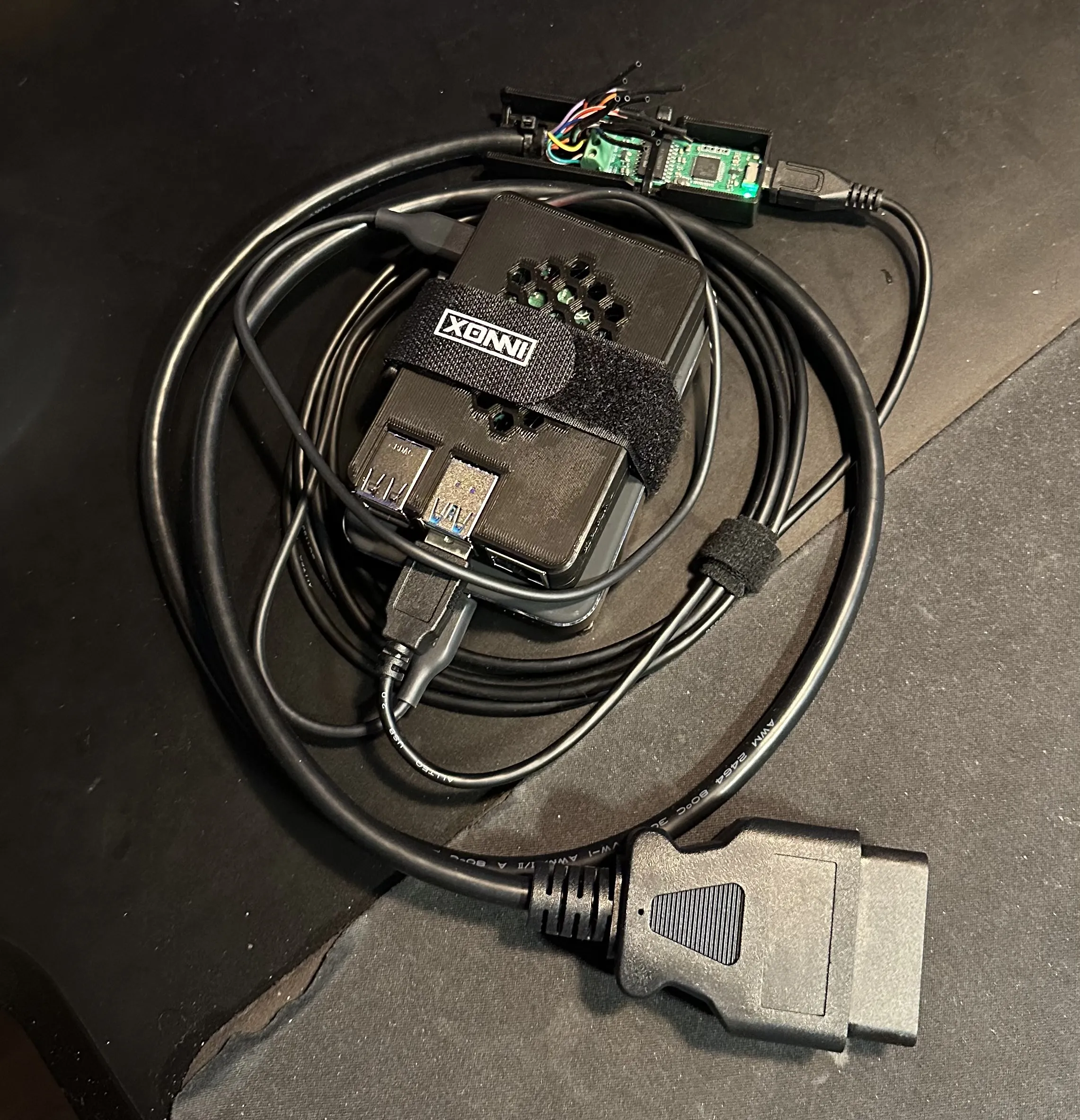
Obviously there is no user interface, but it turns out that SSH’ing into the Pi from my laptop is good enough. When parked in my driveway everything connects to the house WiFi. When on a test drive I lose WiFi reception of course, but accessing the data from the Pi while driving is not a use case I have anyway.
For the first exploration I just had Claude Code write one-off Python scripts on the Pi directly. Eventually these scripts evolved into a proper data logger.
Even though this is a janky setup I quickly found that for me this is actually a much more powerful diagnostic tool than DiagBox. As a software engineer, the lack of a user interface and having to write code to interact with my car is not a downside at all, it is in fact a huge win. It’s a tool that I can adapt to whatever I need at the moment, instead of limiting myself to the manufacturer’s tools and procedures.
Permanent logger
As an aside, I’m working on custom hardware for CAN logging that can stay connected to the OBD-II port permanently. I want historical data from the car in my Grafana dashboards. My theory is that many issues can be spotted in sensor data long before they turn into actual faults, and I intend to find out.
I’m sure such devices already exist, but I will build it myself because:
- This data will go through my own infrastructure only. No third party “cloud” services, no shitty apps that include more behavior tracking than functionality.
- For me the power in such a tool is really in being able to adapt the system to whatever I need instead of limiting myself to whatever a vendor offers.
- CHALLENGE ACCEPTED.
Specs:
- ESP32-based
- Logs CAN traffic
- Logs parameters via active diagnostics
- Data storage on an SD-card
- Offloads logged data to my homelab when parked at the house for offline analysis
- Ultra-low power usage when the car is parked
More on this in the future.
Sources of information
It turns out looking things up takes much less effort than actual reverse-engineering. Manufacturers are mandated to offer the information and tools necessary for independent repair for a “reasonable” price.
It’s not even that expensive, but at Citroën you get access only for a limited amount of time. For a professional it’s not that big of a deal to buy permanent access, but that’s really too expensive for a private individual tinkering on their own car.
This is fine though, I still heavily used the technical documentation, wiring diagrams, and diagnostic software by buying access through Service Box. While I had access I looked up the things I needed, saved myself a ton of work, totally worth it.
Also, there is a lot to learn from the DiagBox files regarding the CAN communication and diagnostic protocols. It includes databases that explain a lot about how to decode the CAN messages from the car.
Which protocol, which wires
I need to figure out how to even communicate with the car. The wiring diagram for the OBD-II connector shows something like this.
┌───────┬───────────────────────────────┬───────────────────────────────────┐│ Pin │ Signal │ Connects to │├───────┼───────────────────────────────┼───────────────────────────────────┤│ 1 │ +12V switched (after-contact) │ — │├───────┼───────────────────────────────┼───────────────────────────────────┤│ 3 │ CAN diagnostic H │ BSI (gateway) │├───────┼───────────────────────────────┼───────────────────────────────────┤│ 4 / 5 │ ground (chassis / electronic) │ — │├───────┼───────────────────────────────┼───────────────────────────────────┤│ 6 │ CAN H Intersystème │ I/S backbone │├───────┼───────────────────────────────┼───────────────────────────────────┤│ 7 │ K-Line │ engine, auto gearbox, add. heater │├───────┼───────────────────────────────┼───────────────────────────────────┤│ 8 │ CAN diagnostic L │ BSI (gateway) │├───────┼───────────────────────────────┼───────────────────────────────────┤│ 12 │ K-Line (K4) │ ESP, hydraulic suspension │├───────┼───────────────────────────────┼───────────────────────────────────┤│ 14 │ CAN L Intersystème │ I/S backbone │├───────┼───────────────────────────────┼───────────────────────────────────┤│ 16 │ +12V permanent │ — │└───────┴───────────────────────────────┴───────────────────────────────────┘Let’s dig into what we see here.
First thing is that there is a CAN bus on pins 6/14 and a K-Line bus on pin 7 as specified in ISO 15031-3. Whatever is on the “Intersystème” bus should respond to EOBD (European On-Board Diagnostics) requests as specified in ISO 15765-4. But there is a K-Line bus as well. K-Line is an older communication bus that was used for OBD before CAN became common on vehicles (ISO 9141-2). Either of those is required to be present. Since both are communication buses for the same purpose, it’s now unclear which one to use. It’s not uncommon for cars from this era (this car is from 2008) to have a mixed architecture with some computers responding to diagnostic requests through the newer CAN and some through the legacy K-Line.
Also noteworthy, we see a second CAN bus on pins 3/8 and a second K-Line bus on pin 12, which are not part of ISO 15031-3. The manufacturer is free to use these pins for basically whatever. The second K-Line apparently connects to a second set of computers, essentially more of the same, not that interesting. But the second CAN bus is called a diagnostic bus, but it’s not part of the EOBD spec, which makes it kinda unclear which bus I need for what.
Specification Soup
So all this stuff is incredibly confusing. Here is some context I desperately needed at this point.
OBD is a stack of specifications that describe how to access on-board diagnostics on vehicles. EOBD is the European version. The legislated application protocol is ISO 15031-5. All somewhat modern cars are mandated to speak this protocol. In addition there are manufacturer-specific diagnostics that go beyond the EOBD spec, and those use either Keyword Protocol 2000 (KWP2000, ISO 14230-3) or the newer Unified Diagnostic Services (UDS, ISO 14229-1). These protocols describe which bits to send and what you can expect to receive back.
The physical layer describes how these bits travel from one place to another through, in this case, electrical signals. This is either K-Line (ISO 14230-1) or the newer CAN (ISO 11898-2).
Specifically for CAN we also have ISO-TP (Transport Layer, ISO 15765-2). This is because CAN frames have a maximum payload of 8 bytes, so if you want to send bigger messages (which both KWP2000 and UDS do) you need to segment the data into multiple frames. ISO-TP describes how to do this. K-Line does not have this segmentation issue since it’s based on streams of bytes instead of streams of frames.
So really what we need to figure out is two things:
- Does this car speak KWP2000 or UDS in addition to EOBD?
- Does this car speak those protocols on K-Line or CAN?
Just try it out I guess
At this point I’m ready to start poking at those buses to see what responds. Luckily the DiagBox databases already answer our two questions: the ECU on this car is diagnosed using KWP2000 over ISO-TP on CAN.
I have a cheap ELM327 clone OBD-II dongle that I could quickly hook up with the Car Scanner app to see what it would detect. It detected generic EOBD over ISO-TP at 500kbit/s, which basically confirms the finding from DiagBox. I couldn’t get it to connect over K-Line, but this could be either because my cheap dongle does not actually support K-Line, even though the listing said it does, or the car just does not use K-Line, even though the wiring diagram specified it.
Anyway, it does not matter because KWP2000 over ISO-TP works, which is perfect since I already have a CAN interface I can use. K-Line would have required buying or building a K-Line interface.
At this point I’m ready to hook up the Raspberry Pi so I can poke at the car from my own code instead of the Car Scanner app. From my first probe script I found that the computers from the engine, gearbox, suspension and ESP all answered on the Intersystème bus. I also saw a ton of activity on this bus in general, especially with the engine running, so pins 6/14 on the OBD connector appear to wire straight into the drivetrain bus. On some cars there is some kind of gateway in between, but not on this car.
Now I was getting curious about the second CAN bus on pins 3/8 that according to the wiring diagram connects to the BSI (Boîtier de Servitude Intelligent, ~intelligent service unit). On other cars this is often called a body control module. From the documentation and DiagBox files it looks like the BSI acts as a gateway for communicating with all the non-drivetrain modules on the car.
I probed pins 3/8 with my oscilloscope first. Both pins seem to hold at ~2.5V which is normal for a CAN bus, but zero activity, so there are no computers broadcasting like on the I/S bus. After hooking up the Pi to this bus I found that the BSI responds to KWP2000 requests at 500kbit/s, and no other computers respond. This is confirmed to be a bus with only the BSI on it, which acts as a communication gateway for all the other modules on the car.
Unattended Logger
Now I have what I need to communicate with the car and decode its messages, so I can get to the original goal. I was trying to figure out what was causing P0011 and P0021 (camshaft position fault) DTCs.
The most likely causes would be either bad control solenoids or bad cam phasers. I really wanted to know which one of these it was, because replacing the phasers is a lot of work, and I didn’t want to take a gamble only to find out the solenoids were the issue. My theory was that the VVT-related parameters from the car would betray the cause.
So I turned my test scripts into an unattended logger. The application starts automatically with the Pi via systemd. It survives being unplugged on both the USB and CAN side. Once it has a working connection to the CAN bus it starts logging traffic as raw hex to disk. It stays in listen-only mode, waits for a set of messages that mark a running engine, then starts a diagnostic session, takes a DTC snapshot, and starts polling camshaft parameters, per-cylinder knock retard, RPM, fuel trims and temperatures.
This allows me to boot up the Pi while I get into the car, hook everything up, go on a test drive, take the Pi back inside, download the data, and analyze the data at my desk.
Learned from the Car
Immediately requesting data again after receiving a response caps at ~50 requests per second. Every time I started driving the diagnostic session got killed by the ECU, presumably to reduce CPU load. Notably the ECU still responds with request denials, so my communication timeouts that would restart the session never got hit. I implemented a wait period of 60 ms between the end of the last response and the start of the next request. Still plenty fast and this fixed the issue.
Also I learned that the ECU won’t respond to EOBD requests while a KWP2000 session is active, so I need to alternate between both to get the full snapshot.
The conclusion here is that these ECUs (Bosch ME7.4.7) have very limited compute capacity, while running timing-sensitive workloads, so you have to be a bit careful to not overload them.
Data Analysis
Another quick Python script decodes the CAN messages from the log and plots it on a graph. This was exactly what I needed!
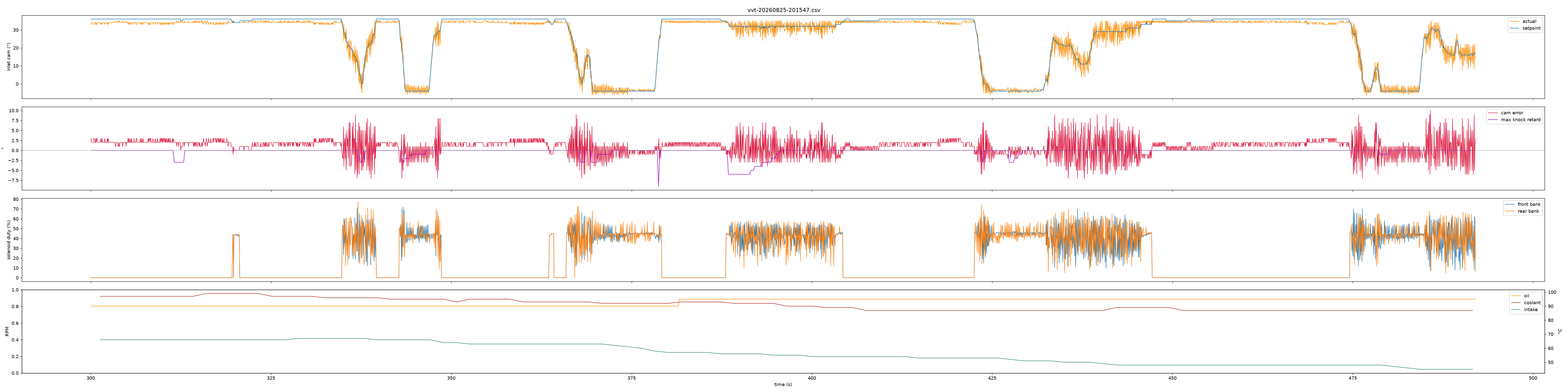
On this car a setpoint of 36° is the fully retarded position where the camshafts are parked when idle or stopped. The camshaft timing gets advanced to about -4° at wide open throttle. The measurements are not perfect, some amount of noise is normal.
Note that when the setpoint is at 36° the actual position jumps a tiny bit between 33° and 35°. This is not perfect but not alarming to me. I would not be surprised if the endstop is at 35° but the computer sets 36° to be sure that the phaser holds position against the endstop. The 1-2° noise is probably an accumulation of measurement errors, rounding errors, and just general flex in the system.
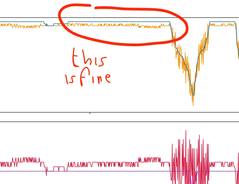
When the setpoint is fully advanced at about -4° the actual position oscillates around the setpoint, which is not really what I want to see.
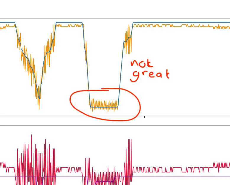
But for any setpoint between both extremes the actual position swings wildly around the setpoint! Note also the position error on the second panel. This to me looks like a classic case of a badly tuned PID loop that is constantly overcorrecting.
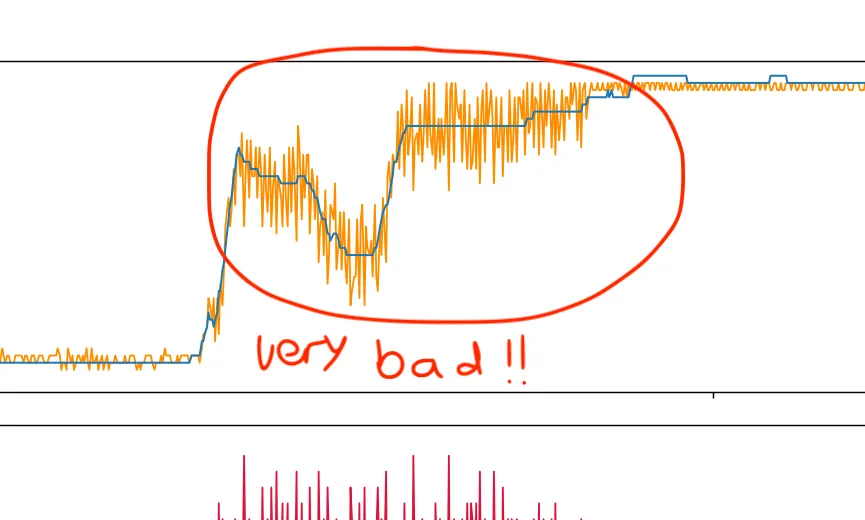
If the camshaft position is hunting like this that would feel like inconsistent power delivery. This is the shudder that I feel from the engine when cruising. It’s fine at idle and fine under high load, because then the phaser is at its endstops, but the cruising regime in the middle is where it shudders.
Of course the PID loop can’t actually be tuned. The calibration is just baked in from the factory. A better way to put it is that the PID loop is not tuned well for the specific solenoid that is on the car. Which is a cheap replica, because the originals don’t exist anymore. I can’t find them anywhere. Apparently the replicas are different enough that they throw off the control loop. We’ve found out-of-spec VVT solenoids.
What now?
I’ve looked for replacement (original) solenoids everywhere but I just can’t find them. These are a known wear item on these engines, there was not much aftermarket supply after Citroën stopped stocking them, and all the supply has simply been used up.
I truly wanted to avoid this outcome at all cost, but I’m afraid…
I’m going to have to engineer my way out of this.